

Fire Flow Testing and Marking of Hydrants – A Technical Guide
4.2 Procedure
• Tests should be made during period of ordinary demand.
• One hydrant, designated the RESIDUAL hydrant, is chosen to be the hydrant where the normal static pressure will be observed with the other hydrants in the group closed, and where the residual pressure will be observed with the other hydrants flowing.
Figure 4.3.4
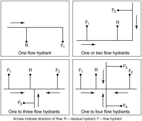
Figure 4.3.4 – Suggested Test Layout for Hydrants
SECTION 4.3.6
• To obtain satisfactory test results of theoretical calculation of expected flows or rated capacities, sufficient discharge should be achieved to cause a drop in pressure at the residual hydrant of at least 25 percent, or to flow the total demand necessary for firefighting purposes.
Section 4.5 Test Procedure
4.5.1 In a typical test, the 200 psi (14 bar) gauge is attached to one of the 2 1/2 in. (65mm) outlets of the residual hydrant using the special cap.
4.5.2 The cock on the gauge piping is opened and the hydrant valve is opened full.
4.5.3 As soon as the air is exhausted from the barrel, the cock is closed.
4.5.4 A reading (static pressure) is taken when the needle comes to rest.
4.5.5 At a given signal, each of the other hydrants is opened in succession with discharge taking place directly from the open hydrant butts.
4.5.6 Hydrants should be opened one at a time.
4.5.7 With all hydrants flowing, water should be allowed to flow for a sufficient amount of time to clear all debris and foreign substances from the stream(s).
4.5.8 At that time, a signal is given to the people at the hydrants to read the pitot pressure of the streams simultaneously while the residual pressure is being read.
4.5.9 The final magnitude of the pressure drop can be controlled by the number of hydrants used and the number of outlets opened on each.
4.5.10 After the readings have been taken, hydrants should be shut down slowly, one at a time, to prevent undue surges.
Section 4.6 Pitot Readings
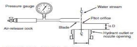
Figure 4.6.9 – Pitot Tube Position
4.6.5 The air chamber on the pitot tube should be kept elevated.
4.6.6 Pitot readings of less than 10 psi (0.7 bar) and more than 30 psi (2.1 bar) should be avoided, if possible.
4.6.7 Opening additional hydrant outlets will aid in controlling the pitot reading.
4.6.8 With dry barrel hydrants, the hydrant valve should be wide open to minimize problems with underground drain valves.
4.6.9 With wet barrel hydrants, the valve for the flowing outlet should be wide open to give a more streamlined flow and more accurate pitot reading. (see figure 4.6.9)
Section 4.7 Determination of Discharge
4.7.1 At the hydrants used for the flow during the test, the discharges from the open butts are determined from measurements of the diameter of the outlets flowed, the pitot pressure, (velocity head) of the streams as indicated by the pitot readings and the coefficient of the outlet being flowed as determined from figure 4.7.1
4.7.2 If flow tubes (stream straighteners) are being utilized, a coefficient of 0.95 is suggested unless the coefficient of the tube is known.

Figure 4.7.1 – Three General Types of Hydrant Outlets and Their Coefficients of Discharge
Table 4.10.1(a) Fire Flow Testing and Marking of Hydrants
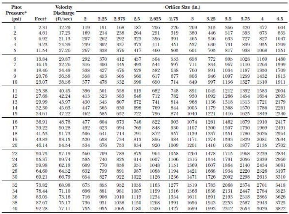
Table 4.10.1(a) – Theoretical Discharge Through Circular Orifices (U.S. Gallons of Water per Minute)
Two Hydrant Flow Tests with a Calibrated Flow Device
 Main Capacity Flow Test
Two-Hydrant Flow Test:
A Main Capacity Test evaluates the water supply of the fire main at the location of the test hydrant. The information derived from this test is used by city planners and contractors to consider the water supply for general use and fire sprinkler systems.
Setup at the Test Hydrant (pressure hydrant, static/residual hydrant):
- Attach gauge cap to the test hydrant. Tighten all other caps.
- Open test hydrant, vent air from hydrant body through the valve on the gauge cap assembly. Close it when air is vented.
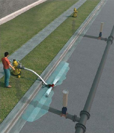
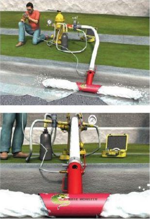
At the Flow Hydrant
- Set the Little Hose Monster™ with gauge to the Pitotless Nozzle™ in an appropriate location for flowing water.
- Attach Remote Reader and gauge to the Pitotless Nozzle.
- Attach hydrant gate valve to the hydrant.
- Tighten other caps.
- Attach the hose to the Pitotless Nozzle and Little Hose Monster assembly.
Conduct the Test
- Record static pressure reading from gauge cap. (Test Hydrant)
- Open flow hydrant fully.
- When the flow rate stabilizes,
- Record nozzle pressure from the flow reader. (Flow Hydrant)
- Record the residual pressure reading from the gauge cap. (Test Hydrant)
At this point, the test is complete
- Slowly close Flow Hydrant. Remove test equipment from hydrant. Replace and tighten cap. If the hydrant is a dry barrel type, note that water drains properly from the hydrant.
- Record the number of minutes that water was flowing. This can be used to account for the amount of water used during the flow test.
At the Test Hydrant
- Close the hydrant. Remove gauge cap and replace hydrant cap. If the hydrant is a dry barrel type, note that the water drains properly from the hydrant.
Hose Friction Loss
In summary, the Test Flows will be different, but will not affect the flow test. The Hose Monster and hose will result in a lower test flow-rate and a higher residual pressure. When all data is considered, the flow tests result in the same predicted flow-rates
How much is the friction loss when I use a hose?
There is friction loss when flowing through a hose, but in a hydrant flow test, it doesn’t mater. The purpose of a hydrant flow test is to evaluate the water supply, or the flow-rate that will be available when the system is brough down to 20 psi residual.
A hydrant flow test requires three measurements: static pressure, residual pressure and test flow-rate. The reading from the gauge cap in the residual hydrant gives you static pressure and residual pressure. The Pitotless Nozzle™ or Hose Monster™ gives you the test-flow rate.
The fiction loss created in the hose results in a lower test flow-rate and a greater residual pressure. This will not affect the predicted flow at 20psi as long as there is a sufficient drop in static-to-residual pressure. NFPA 291, 4,3,6, 2016 recommends a drop of at least 25% from static to residual pressure. AWWA M17 recommends a drop of at least 10 psi from static to residual pressure.
To illustrate that friction loss does note have an effect on the predicted flow-rate:
1. Test #1 measures the test flow through an open hydrant nozzle with a hand held pitot.
• Static — 85psi
• Residual — 60psi
• Pitot — 36psi
• Test flow — 1007GPM
Predicted flow at 20psi = 1687GMP
2. Test #2 measures the test flow through 1 1/2″ x 10′ hose and the 2 1/2″ Hose Monster.
• Static — 85psi
• Residual — 70psi
• Pitot — 20psi
• Test flow — 764GPM
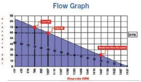 Predicted flow at 20psi = 1687GMP
- Static pressure is equal in both tests. Flow test equipment does not affect static pressure.
- Test flow in Test #2 is less than in Test #1 because of the friction loss in 10′ of hose.
- Residual pressure in Test #2 is greater than in Test #1. The friction loss in the hose causes a backpressure which increases residual pressure. The higher the residual pressure compensates for the lower test flow-rate.
- Both flow tests result in a predicted flow at 20psi that is equal. Test points from both tests fall on the same line of the graph.
Hydrant Testing Pitfalls
- Water gauges not calibrated.
- Insufficient pressure dop on residual hydrant.
- Elevation differential between test and residual hydrant not recorded.
- Hydrant butt type not determined.
- Hydrant test worksheet incomplete.
